
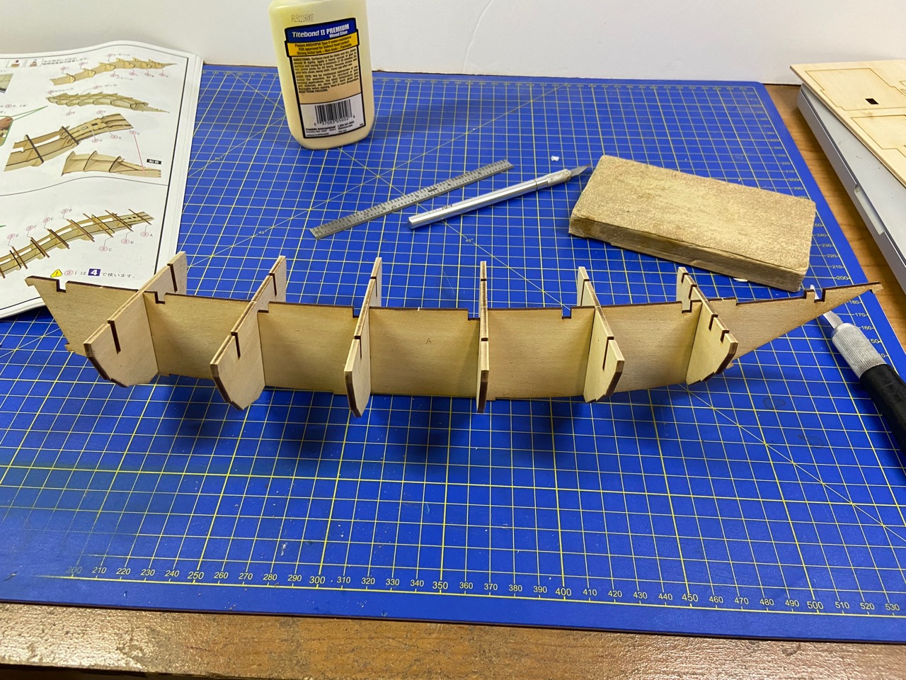
I’m taking it easy on getting this new model kit started. Last time I posted, I really only had cut out the initial parts I needed and then dry-fit them together. This week, I glued together the basic hull frames, using machinists squares to check and set alignment. I used Titebond wood glue for this work.
I spent a lot of time trying to decide what I wanted to do with the bow and transom pieces. These pieces have holes in them that alignment tabs in the keel piece will lock into. The thing I don’t like about this, is that they are then visible on the finished model. As far as I can tell, there are 5 tabs total that will be visible on the completed model, as designed.
Since I’m dying the wood, these tabs shouldn’t be as noticeable as on a kit built straight from the box. Still, I’ve considered solutions, and one is to thickness sand the bow and transom pieces down by 1mm, then use 1mm sheet wood to cover them. The covering wood will have no holes in it, so no tabs will be visible. In order that everything still fits together, I will have to file the tabs down by 1mm.
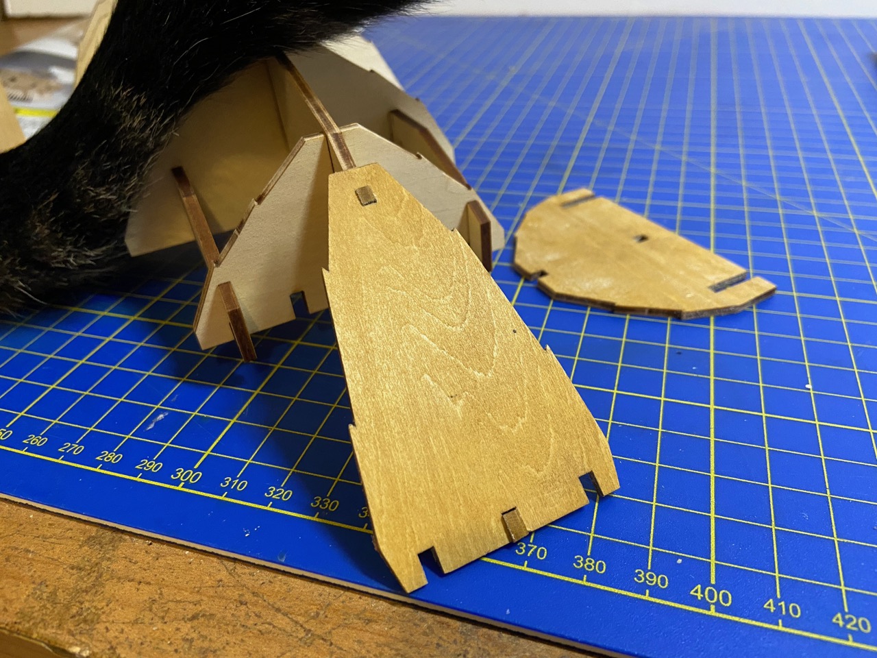
You can see from the photo below how the tabs stick out now.

About the Bow
Now, there is one other thing about the bow that I’m considering changing. The Woody Joe kit is based on the museum model in the Saga Prefectural Nagoya Castle Museum, but I’m sure that model has some simplifications, as I believe I’ve mentioned earlier. One of those possible simplifications is the design of the bow.
Many paintings and museum models usually show the bow of the Atakebune to be made up sections, often overlapping ones. I’ve been playing around with the idea of introducing that feature to this model. Of course, paintings and museum models are not real evidence, since the paintings and models are pretty modern reconstructions.

The two main types of bow of the Atakebune. On the left is the type of bow shown by the Woody Joe model. Note it appears here as two large pieces that are mounted flush.
Based on this illustration from the book Wasen II by Professor Kenji Ishii, it would be simple to represent the bow as shown on the left. Since I’m already planning to sheathe the face of the bow plate, it would be simple to use two pieces of wood to recreate this appearance.
About the Large Hull Planks
One thing that was brought up recently by a fellow ship modeler was the apparently simplistic representation of the hull planking on models of Japanese boats, particularly that of the larger ones like the Atakebune. The idea was that there’s a desire on the part of western ship modelers for more detail, and that the large single sheet planks of the Atakebune kits hull wasn’t exactly realistic. So, I’ve thought about this for a while.
It’s true that Woody Joe kits lean towards easier construction, and trade-offs most certainly have been made regarding the inclusion of various details for lower cost of design work, materials, and easier assembly. This is true, to some degree, of any kit manufacturer. But, how were the hull planks really made up?
These large panels were certainly not made from one single sheet of wood, and must have been made up of various pieces fastened together. How large were the timbers that were available? How were they laid out to form these large panels? How were they joined together? How were the ends of timbers fastened together? Probably, nobody knows for sure. But, there are some examples we can follow, assuming that these are correct, or at least plausible.
One excellent example is to look at one of the replica coast transports that were built in the past few decades. While these are not Atakebune, the way they are constructed at least gives us something to possibly follow. The best example of these today is the Hakusanmaru, on Sado Island. This is the best preserved of the replica bezaisen, as the coastal transports were called.
I visited the ship in 2016 and took a lot of photos and tried to develop an understanding of the way these ships were built. The details of the structure is very complex, and what your seeing in these photos of the lower hull, is essentially a covering planking that hides and possibly protects the actual structural planking.


At the Hakusanmaru museum, there’s a representation of the cross section of the hull which tells us a lot more about how the planks are fastened together, and the general scale of the wood that forms the main structure of the ship.

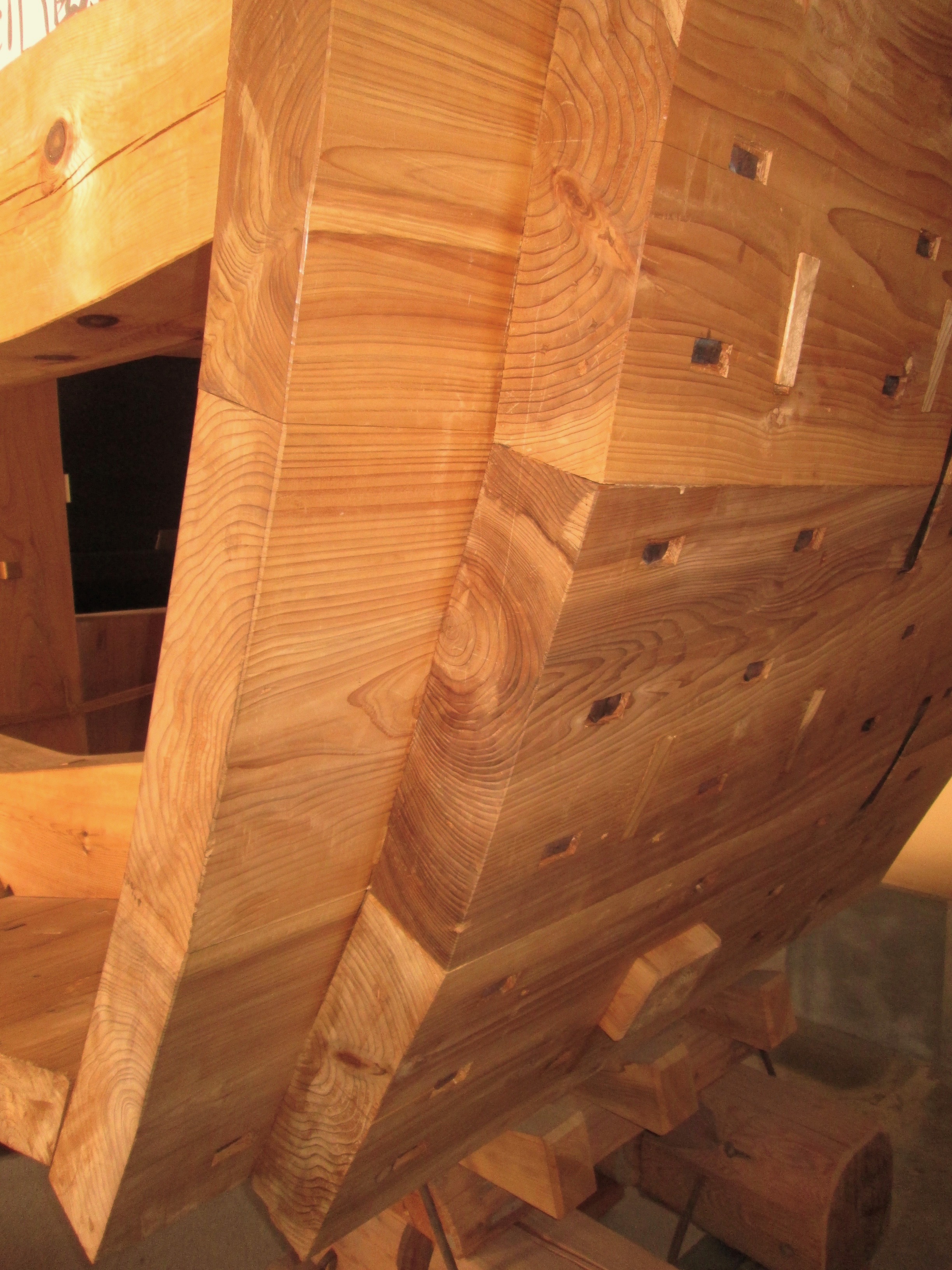

Again, this is a cutaway of the 25meter long bezaisen replica ship, not a 50meter long Atakebune. Their hull shapes, they are built for different purposes, and all. But, it gives you an idea of what a ship structure looks like with heavy planks and no frames.
As I pointed out earlier, this bezaisen had a kind of finish planking that was much lighter wood, and this hid these heavy iron nails. This kind of outer planking may or may not have been present on the Atakebune. And, probably, all Atakebune were different, and more prominent ones may have had a nicer finish. But, one things is clear. There are no scarf joints in these planks. There are overlapping joints in the structural planking. In the finish planking, there are simple butt joints, not staggered in any way.
But, the whole question of planking detail may be more complicated than it needs to be. As illustrated in the photos above, the Japanese shipwrights generally didn’t caulk between planks the way their western counterparts did, except possibly at the chine, which are the sharp angle changes in the cross-section of the hull. So, there is little to show of the seam between adjacent planks.
In my own experience, I have scratch built models of Japanese boats where a wide board is made up of two edge-fastened planks, and the only way you can tell that there are two pieces is really because the difference in the grain and figuring of the wood is visible, but only barely, and that’s at 1/10 scale. At any larger scale, the seam would be completely invisible.
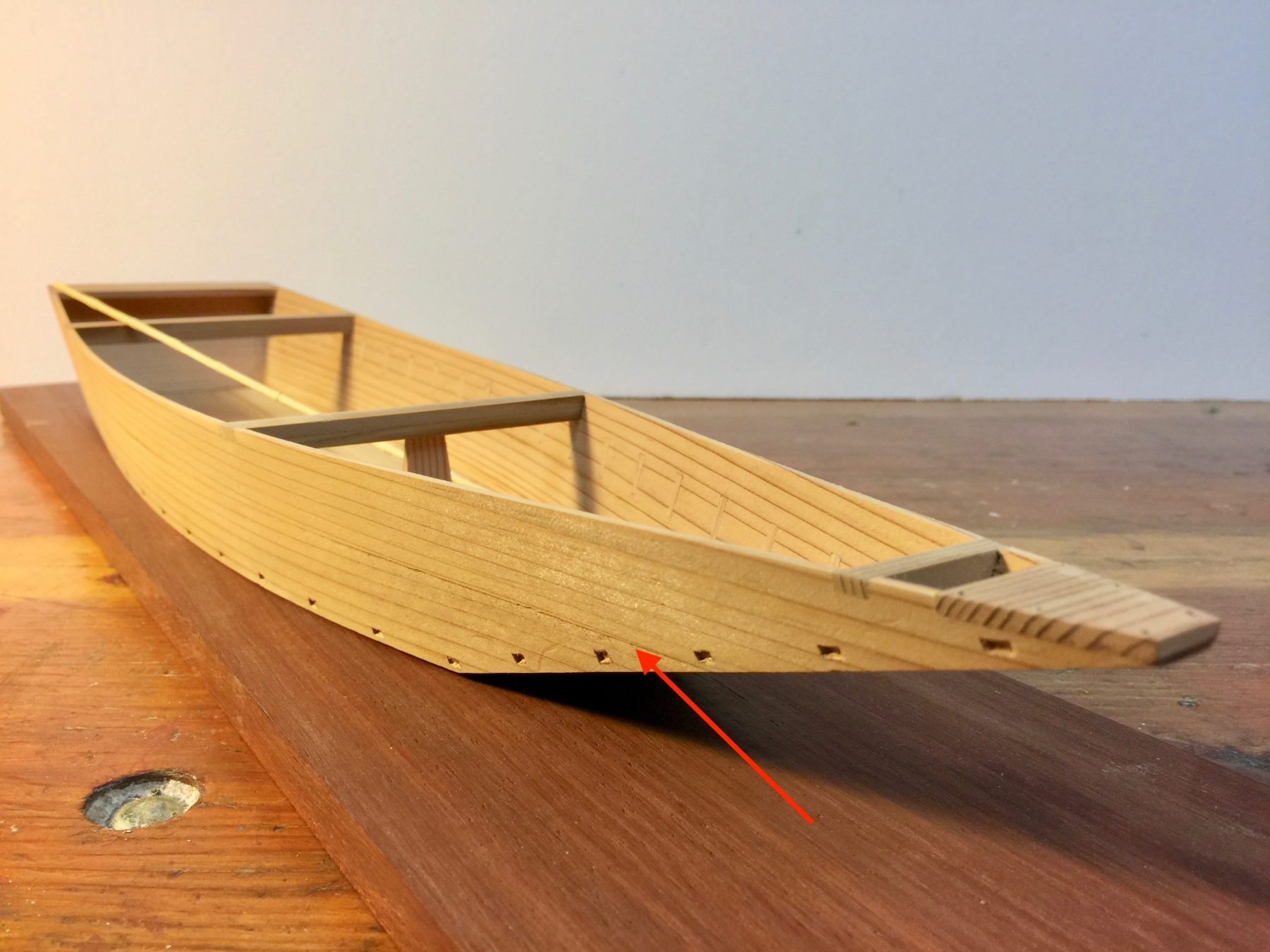
My Hozugawa Ayubune model in 1/10 scale. The hull is made up of 2 planks on each side, and you can barely see any seam between the planks at this scale.
Now, the length of the boards may be another matter. It’s doubtful that an Atakebune hull was made of continuous planks, in this case, 50-meters long. Looking at the paintings of the large Edo period Hiratabune, which were cargo riverboats, they were up to about 24 meters long. At this length, the painting shows the two overlapping joints in the hull planking, making each plank section about 8 meters long.

The Hiratabune was a 24 meter long Edo period cargo riverboat. Note the overlapping hull planks.
So, probably, on an Atakebune, there is likely some fastening and overlap of planks like that shown in the Hiratabune illustration above. On a large hull, assuming longer planks were used, the number of these overlaps are minimized. And at 10 meter long planks, on the 50 meter long Atakebune, there would be about 4 of these overlaps. Of course, there would be fewer if they could manage to use longer plank.
However, if the hull of the Atakebune was finished the way the Hakusanmaru is finished with a covering of thin, narrow planks covering any fastenings and any of these plank overlaps, then at 1/100 scale, you wouldn’t reasonably be able to identify ANY planks at all, and it would look like one solid sheet of wood.

Saga Prefectural Nagoya Castle Museum model.
But, I suppose if you want to assume otherwise and want fastenings and planks to show, there’s a great example in the model of an Atakebune called the Atakemaru. I found photos on Internet, and I’m sorry to say I don’t know where they specifically came from. But, it’s a beautiful model, and shows the large planking overlaps, and some finer planking detail. Is this accurate at all? I can’t say for sure. Certainly, it looks nice. So, maybe some builders will want to try to modify this Woody Joe kit into something more like that.
Back to My Model
For my own model, I’m pretty well sticking with the kit on the hull planking, though I may change the bow and transom boards a little as I mentioned earlier. But, before I get too far along, I’ve decided that I need to test fit things together to get a better understanding of what I might be able to modify without too much difficulty. So, I basically began taping the model together, temporarily fittings pieces into place.

There are essentially three distinct parts of this model: The lower hull, the boxy upper hull structure, and the castle structure. These can actually be built separately and out of order, and I’m considering doing just that. This will buy me some time to figure out what things I want to modify, since the castle-like structure should work pretty well, as is, and setting into place should help me gauge what I can do to the upper hull box structure to make it more unique.
In the meantime, I’ve dyed all the laser-cut sheets using Transtint wood dye. I’ve been using this stuff for years now. My mixture is 24 drops of Dark Vintage Maple to 9 drops of Amber, thinned down in a 2oz jar of denatured alcohol. The nice thing about using wood dye versus stain, is that dye does not affect glue joints, so can be applied before gluing parts together.
