
Something I didn’t mention last time was that I had cut a paper pattern for the shiki and rubber-cemented it to the assembled . I then cut the wood to the pattern. Since the plans I have show the lines to the inside of the planking, I left the pice a little long at the aft end, as the bottom extends slightly beyond the transom.
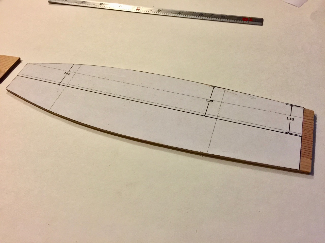
Shiki with pattern, and cut to shape, with extension at the aft end
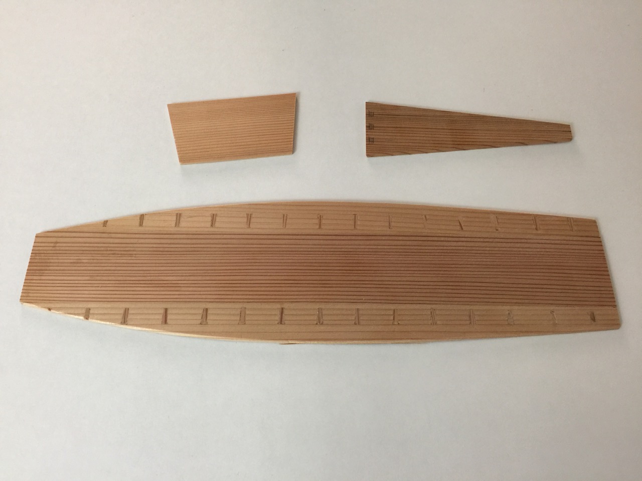
The final pieces are ready for assembly. As on the real boat, the hull planks will be shaped in place. Note that I also cut mortises for the bow plank, which I’m told is called the omote no tate ita. I’m going to have to find the kanji to make sure I know what this really means. The same goes for the transom, or tomo no tate ita, but in other regions is called the todate.
Pieces these parts together in their proper angles presented a challenge. Especially since the hull planks need to be shaped in place on the boat. The real boatbuilders built the boats upright, and used wedges, iron dogs (like big staples), clamps and posts to push and hold things into place.
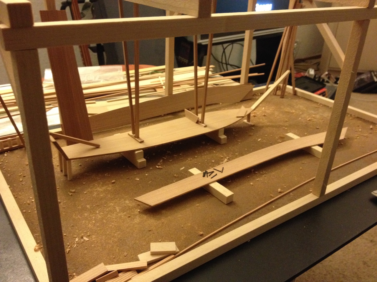
My traditional boatbuilder’s workshop diorama, showing a bekabune under construction
As a model builder, the best solution was to build this model on a mold, though without gluing or drilling into the model, it would be a challenge to hold everything in place.
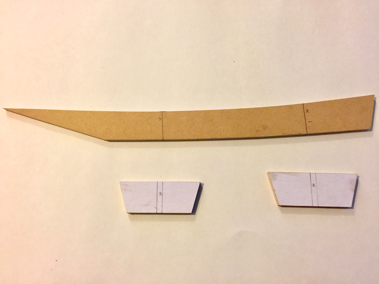
I started with a longitudinal pattern, which would give me the angles for the bow and stern planks, as well as the proper curve of the shiki. I marked the only two station lines on the drawings and cut the cross-wise formers to shape based on the patterns I drew earlier.
A scroll saw and bench sander made quick work of the MDF particle board formers, and the station formers were cut up and glued into place. In the meantime, since the bottom has a slight curve to it, I wet the wood a little and used a fixture I made for holding it into place as the wood dried. It was important not to get the wood too wet, just damp, to keep it from dissolving the wood glue, as I only used original Titebond, not one of the more water resistant versions.

In order to hold the transom piece into place, I had to come up with some kind of notched piece that I pinned into place on the centerline former. At the bow, a simple clamp held it into place. The pieces were glue together and held on the temporary former with rubber bands as the glue dried.

Once dried, the tricky part began, as I had to hold a piece of card stock into place well enough for me to trace a rough outline for the hull planks on it. Not being blessed with 4 hands, I decided to try making a fixture to hold the assembly into place.

The base fixture is a simple board with a clamp that’s designed to hold the former securely. It’s nothing more than two pieces of MDF with a small piece at one side that’s the thickness of the centerline former, all glued together and down to a baseboard.

The clamp and the former are drilled through so that I can run a clamping screw through them. I drew registration marks on the pieces to make alignment easier.

The bottom assembly could now be held somewhat securely, allowing me to work on it and transport it without damage.
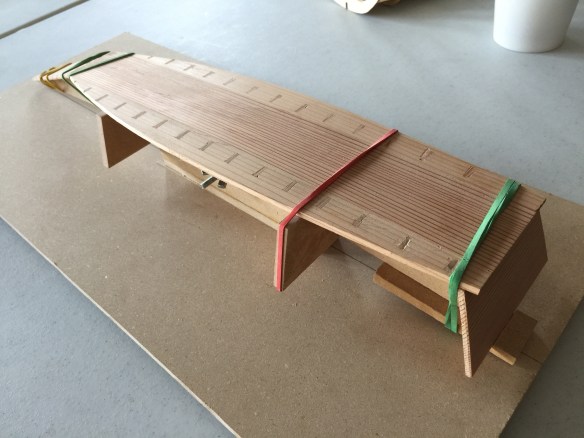
Ayubune model with former clamped to the baseboard fixture
The next step will be to make the hull planks.
