
The Rudder
One of the sub-assemblies that can easily be worked on at any time is the large rudder. The detail in the drawings is very simple, but I felt that it should be very similar to other large rudders used on larger vessels. With the
I made mine from three planks glued edge to edge and cut to the shape of the plans. I then attached a rudder post that I cut round and then tapered toward the bottom. To hold the planks of the rudder together, I took example from the Woody Joe Higaki Kaisen kit I built a few years ago, and added three cross-pieces as shown in the following photo.
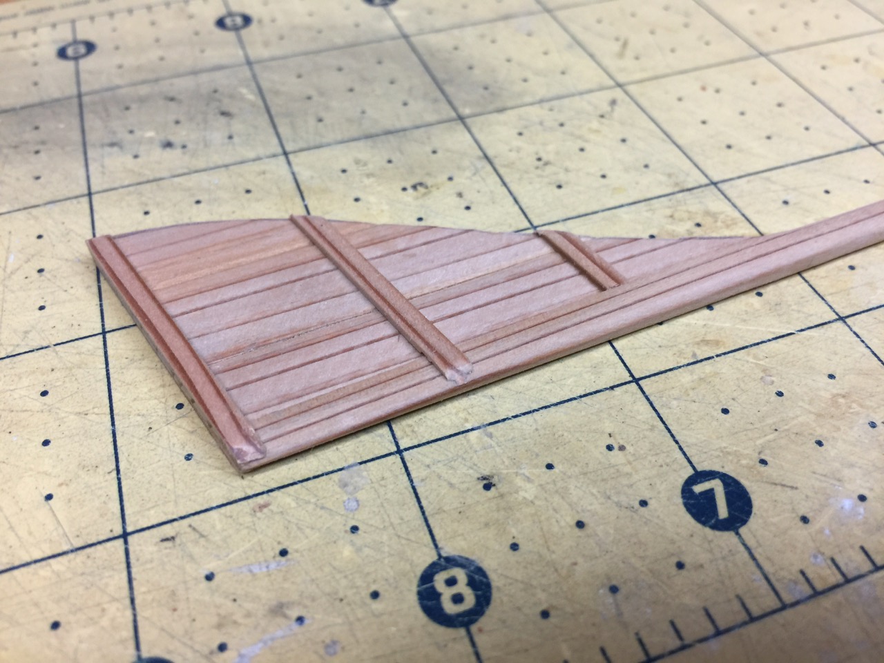
I don’t know what amount of detail to add yet, so I just left the rudder assembly as is.
Fixing the Bulwarks
As I mentioned in my last post, the bulwarks of the Kobaya rises sharply at the stern.
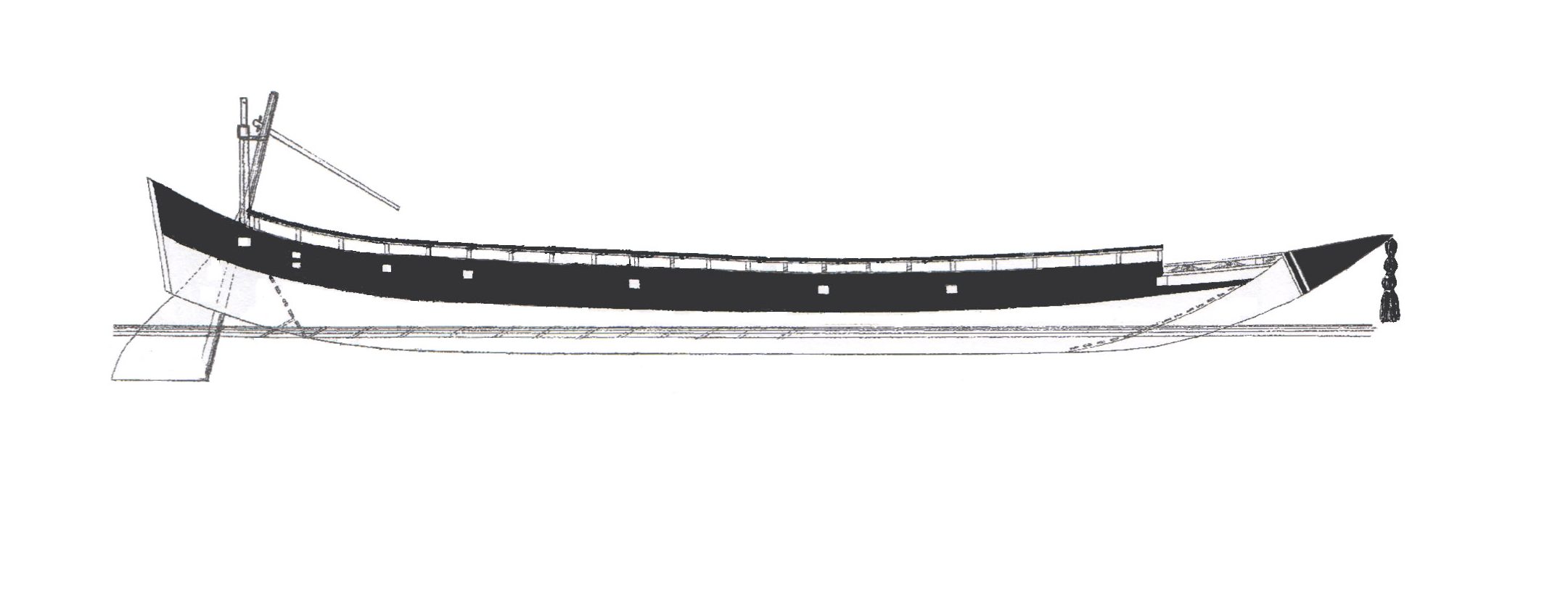
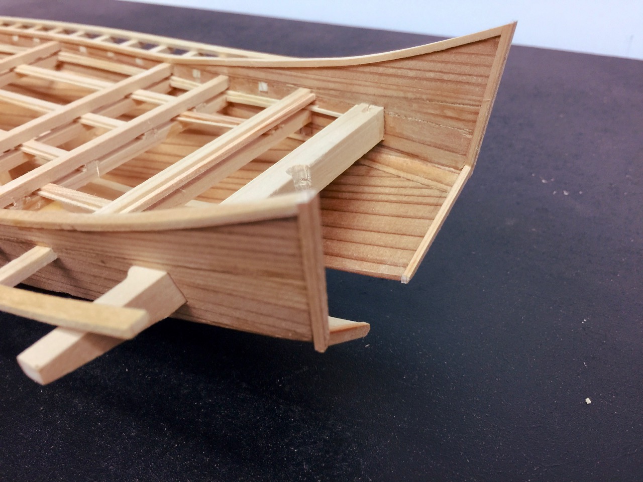
When building this model, I intentionally kept the stern somewhat flat. I was originally going to fix the flatness, but then I realized that I could use the flatness of the hull to my advantage. By leaving it alone, I could simply notch the upper edge of the hull for the fitting of the beams. Had I not done this, I would have had to carefully cut holes for the beams instead, and it would have been much more difficult to keep the installed beams straight in both the horizontal and vertical positions.
Once the beams were installed, it was a fairly simple matter to cut a couple pieces of sheet wood and shape them and fit them into place. Below, you can see the portion of the hull that rises up above the row of beams.
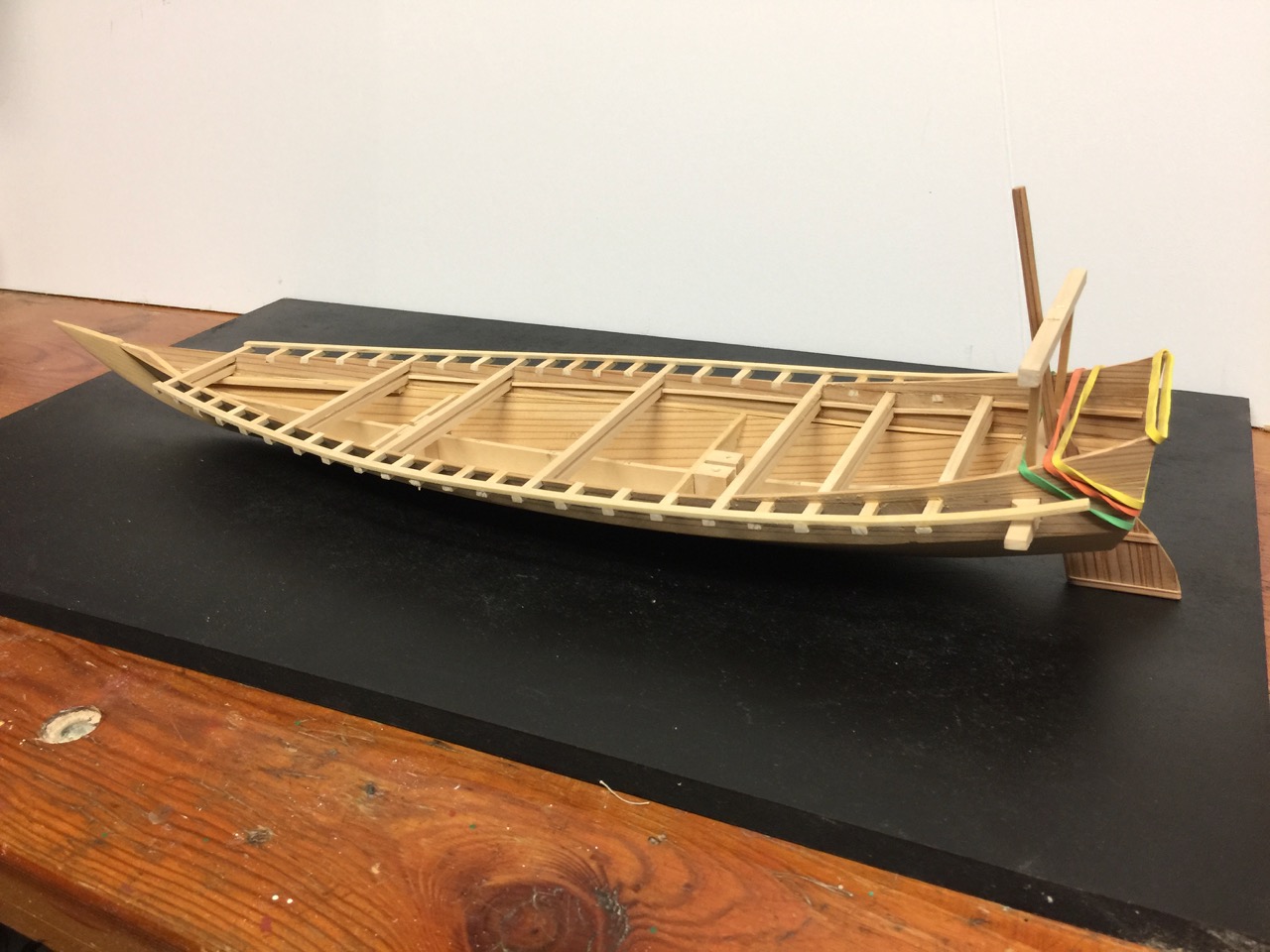 Glueing the new bulwarks pieces into place gave me an opportunity to try to pull the upper hull planks to a more vertical position, which is why I have the rubber bands mounted.
Mooring Beam and Caprail
There was one final beam that pierces the hull that I needed to complete.

I’m not sure what this beam is called. On small boats, I’ve seen the term katsunagi used. But, on coastal transports, these beams at the bow are called kannuki.
Floor Joists
Here is one feature where having built Woody Joe’s Higakikaisen kit has really helped. These are the longitudinal beams that run between the beams and provide the primary support for the deck planks.
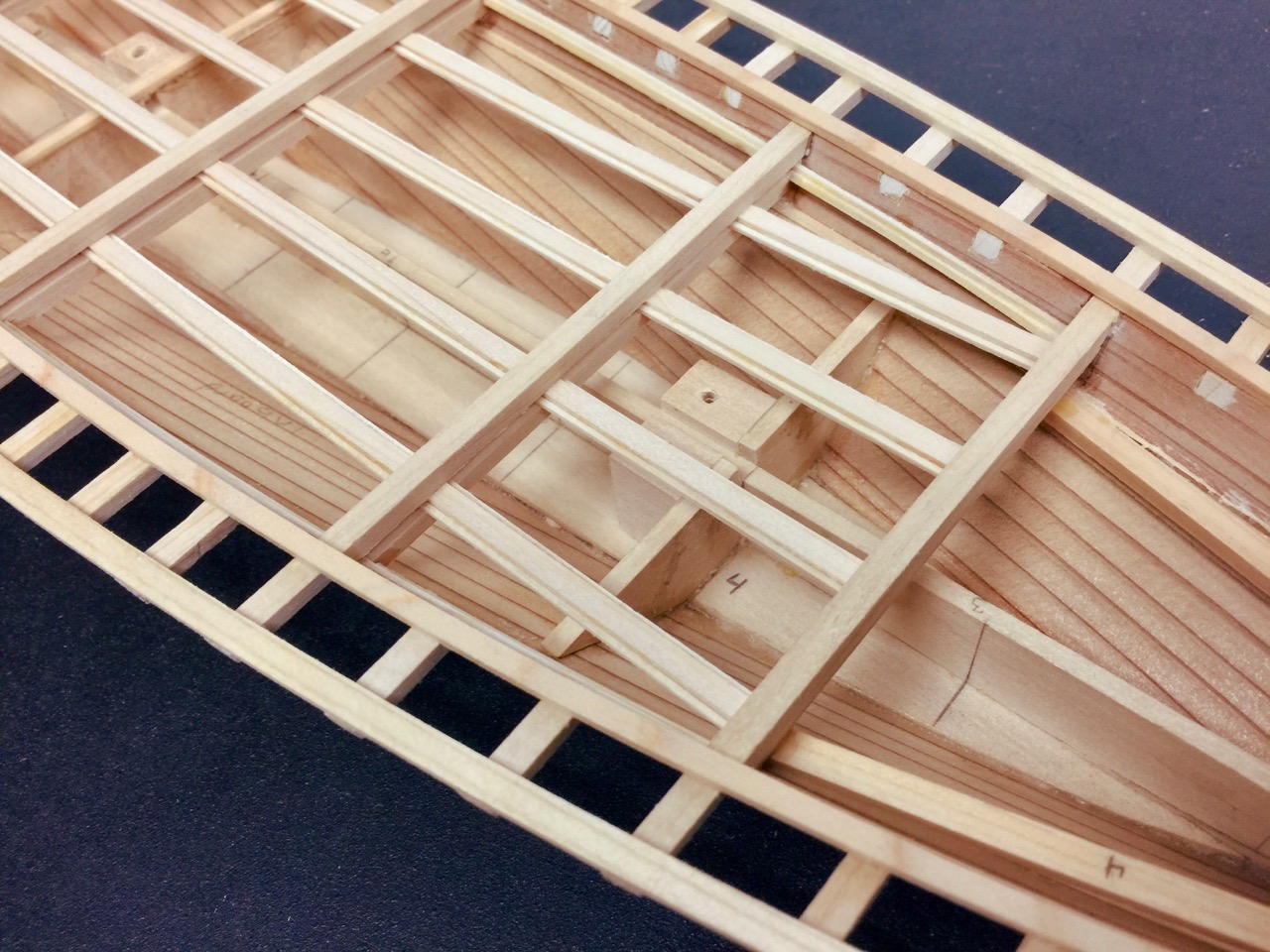
I took a simple route and ran these joists as full length pieces, sandwiched between the upper and lower cross beams. Then I took thin square stock strips and glued them to the side of these joists, so that the bottoms of these strips were flush with the bottoms of the joists. The planks themselves will the ride directly on these strips, and the tops of the planks will then be flush with the tops of the joists.
Near the bow, there is a sunken deck section, so supports were layed underneath the lower beams for the planks to rest on there.
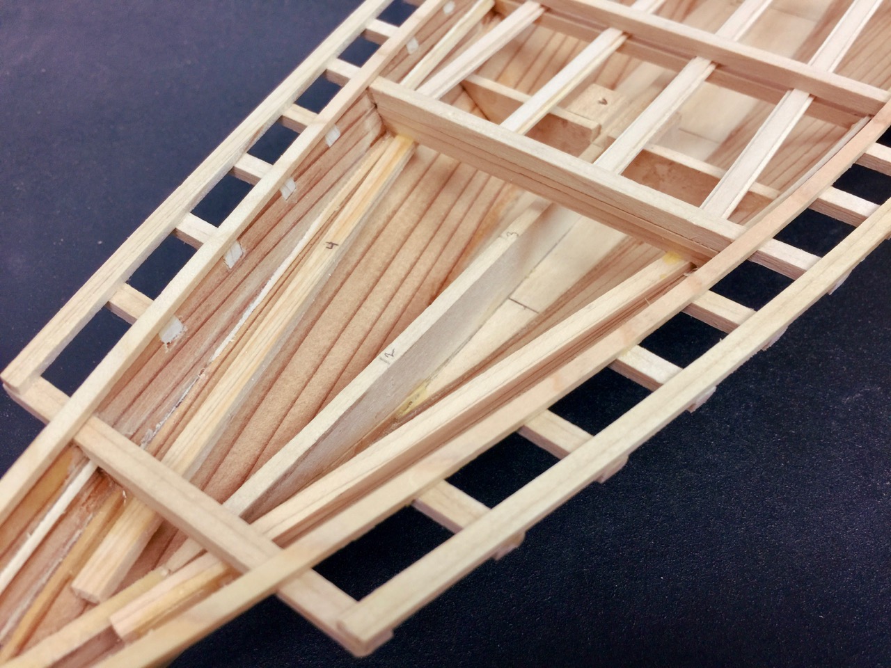
Note that I also had to add some support strips along the hull itself. This was a little bit trickier given the curvature of the hull. But, I think I managed to install them okay.
In my next post, I’ll discuss some of the issues of painting the model and what I found about the paint scheme on the Paris drawings.
