
If you look at the Paris drawings, you will see that there are seven pairs of main beams across the hull, not including the otoko, or great beam, at the stern. In each pair, there is one beam above and one below. The lower beam runs between hull planks. The upper beam goes through the hull planks and supports the rail assembly, which supports the yokes for the sculling oars.
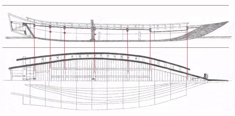
Below, you can see a general cross-section of the hull. There are actually three beams running the width of the hull. Since I already have the internal framework, I don’t need the lowest most beam, so I’m calling the one just under the deck the Lower Beam.
There are also several short longitudinal beams show in cross-section below, but I’ll be dealing with these later when I begin dealing with the deck.

While the diagrams here don’t show it, the lower beams should mortise into the hull planks, locking into place, and adding a lot of strength to the structure. Given the scale of this model and the type of wood I’m using, I decided not to cut through the hull planks. Instead, the lower beams will simply be glued into place, and will help support the deck.
It took me a while to figure out how I would define the actual position of the deck. Then, I realized that the upper beams could define all of that for me. The vertical position of the upper beams is very simple – the top edges can just line up with the top edges of the hull planks, as I can lay down a rail just on top of that. Assuming the deck is just underneath the upper beams, the lower beams will ride slightly below the deck. Of course, this all requires the hull planking to be nice and even and as correctly shaped as possible.
Installing Beams
With the beam locations defined in the drawings, I cut the notches in the hull for the upper beams. For the thickness of the beams, I noted that there seemed to be some differences between the various plan views, so I did my best to figure out something that would work well for the model.
I ended up with beams 4mm square in cross-section. But, I decided to make these more rectangular in cross-section outside the hull, so I maintained the same width, but made them closer to 2.7mm thick. The notches would be cut to a depth of 2.7mm, so the beams were cut to lock into place.
In addition to the full length upper beams, you may note that there are a number of short beams that extend out from the hull planks to support the rails at the sides of the ship. These will be made the same thickness as the outboard portions of the full-length beams, 4mm x 2.7mm.
I cut the full-length beams overly long, but made each one I needed and temporarily held them into place with rubber bands. Then, I cut the lower beams and fit them into place using a temporary wooden spacer to help me maintain proper spacing between the upper and lower beams. I then glued the lower beams into place using thick CA glue. While this discolored the wood slightly, this was all below deck level, so it wouldn’t be visible on the final model.


After this, I had to contemplate the next steps a bit. I was anxious to start dealing with the deck planking, but I also need to the rails and the short beams that support them. I also noted that the stern of my hull doesn’t rise up as much as in the Paris drawings. Also, the deck doesn’t follow that rise. But, I figured that I could continue with the deck construction the way I have the model now, and then I may add extentions to the hull aft, after the beams for the rails are installed. After all, it would easier to add them at this stage, rather than to modify the hull first and then try to figure out where to cut through it to add the beams there.
Of all the beams, though, the biggest problem I’m going to have is with the ōtoko, or the great beam, at the stern. In reality, this would have been installed before the hull planking, as the ends of the beam pierce the upper planks. I can’t simply cut notches to mount this one, so I may have to fake the construction a little. I’m putting off that construction until a bit later.
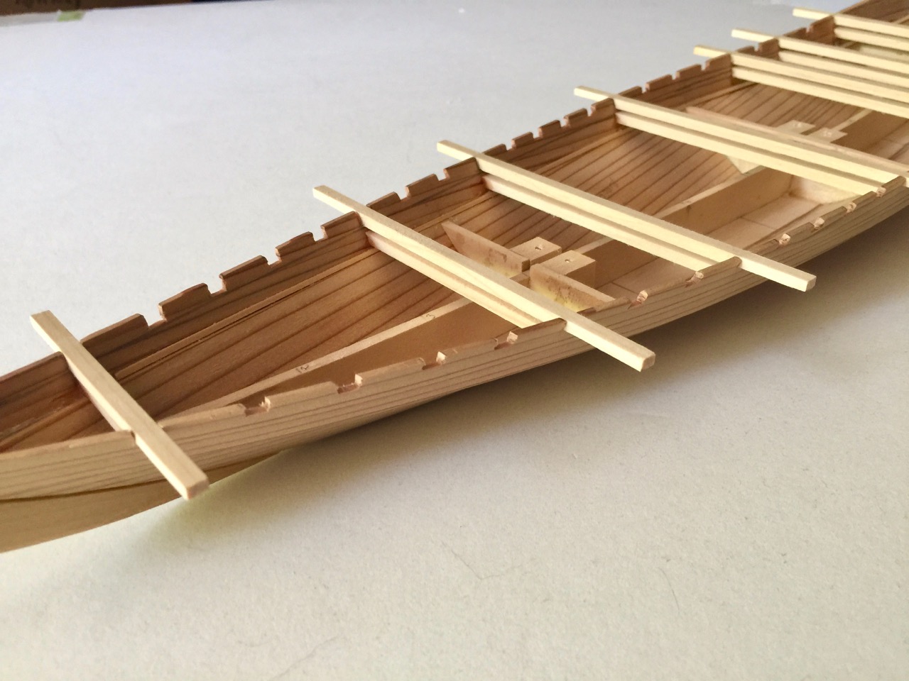
It took a bit of work to get the spacing even between the notches. I tested the notches by placing beams into them and visually checking to make sure the alignment looked good. Each set of notches between two beams are unique, and the spacing between them may be slightly different than the spacing of the notches between a different pair of full-length beams. But, the differences appear to be pretty small, and that’s how they are on the drawings if you measure closely.
The full-length beams are now glued into place using Titebond and I have to decide whether to add the beams for the rails first or the ones for deck planks. In any case, the blog posts have caught up with my project progress, so now it’s time to look at this all and consider what to do next.

Reblogged this on The Ship Modeler and commented:
I decided to take the day and update most of my documentation, so here’s the current Japanese traditional boat project I’m working on. I have another project with some slow research and decision making, but this is one that I basically have all the information on, since it is based on a pretty complete set of drawings.
This entry brings the blog up to date with the project’s progress.
LikeLike
Just a wonderful website. Thankyou for making details of traditional Japanese boats available!
it is not easy to find information in English.
LikeLike