Building a Gozabune (Kobaya) from Paris Plans – Part 3

If you look at the Paris drawings, you will see that there are seven pairs of main beams across the hull, not including the otoko, or great beam, at the stern. In each pair, there is one beam above and one below. The lower beam runs between hull planks. The upper beam goes through the hull planks and supports the rail assembly, which supports the yokes for the sculling oars.

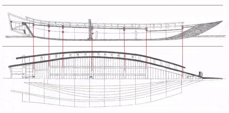
Below, you can see a general cross-section of the hull. There are actually three beams running the width of the hull. Since I already have the internal framework, I don’t need the lowest most beam, so I’m calling the one just under the deck the Lower Beam.

There are also several short longitudinal beams show in cross-section below, but I’ll be dealing with these later when I begin dealing with the deck.

Continue reading

Building a Gozabune (Kobaya) from Paris Plans – Part 2

I have seen the coastal transport replica on Sado Island, the bezaisen Hakusan Maru, up close, inside and out. The construction seemed much different from the smaller hacchoro, the bonito fishing boat replica that I visited in Yaizu. This gozabune is about 17 meters long, the hacchoro of yaizu was about 13 meters long, and the Hakusan Maru, about

Lower Planks

From building the Hozugawa-bune and the Bekabune, I learned that a card stock pattern is the best way to get the shape of the lower edge of the lower plank. Taping the cardboard into place, I used a pencil to mark the outer line where the bottom and the lower plank came in contact. Then, measuring the width of the station lines in the Paris drawings, I marked out the points on the cardboard template and drew in the curve of the upper edge of the plank.

Continue reading

Building the Urayasu Bekabune Model – Final

At the bow was the first challenge of cutting a small square hole for the small beam at the bow. I made sure my chisel was good and sharp and lightly cut the shape, little by little. Too much pressure can chip or split the wood, particularly on the back side of the cut, so this took a lot of care.

With the first hole cut to size, the alignment of the opposite hole was aided by running the beam into place to see where it lined up. It was then cut in the same manner.

Continue reading